Indledning
Airflow pattern visualization and verification are essential for maintaining cleanroom integrity, especially in Grade A and ISO 5 environments where laminar airflow is expected to protect critical zones from contamination. Your original article correctly identifies airflow failures as a major root cause of contamination, environmental monitoring alerts, and regulatory observations. :contentReference[oaicite:2]{index=2}
A room can meet particle limits during one test and still fail operationally if airflow is unstable, obstructed, or short-circuited. That is why airflow verification should not be treated as a visual extra. It is a primary physical-control check.
Airflow Pattern Fundamentals
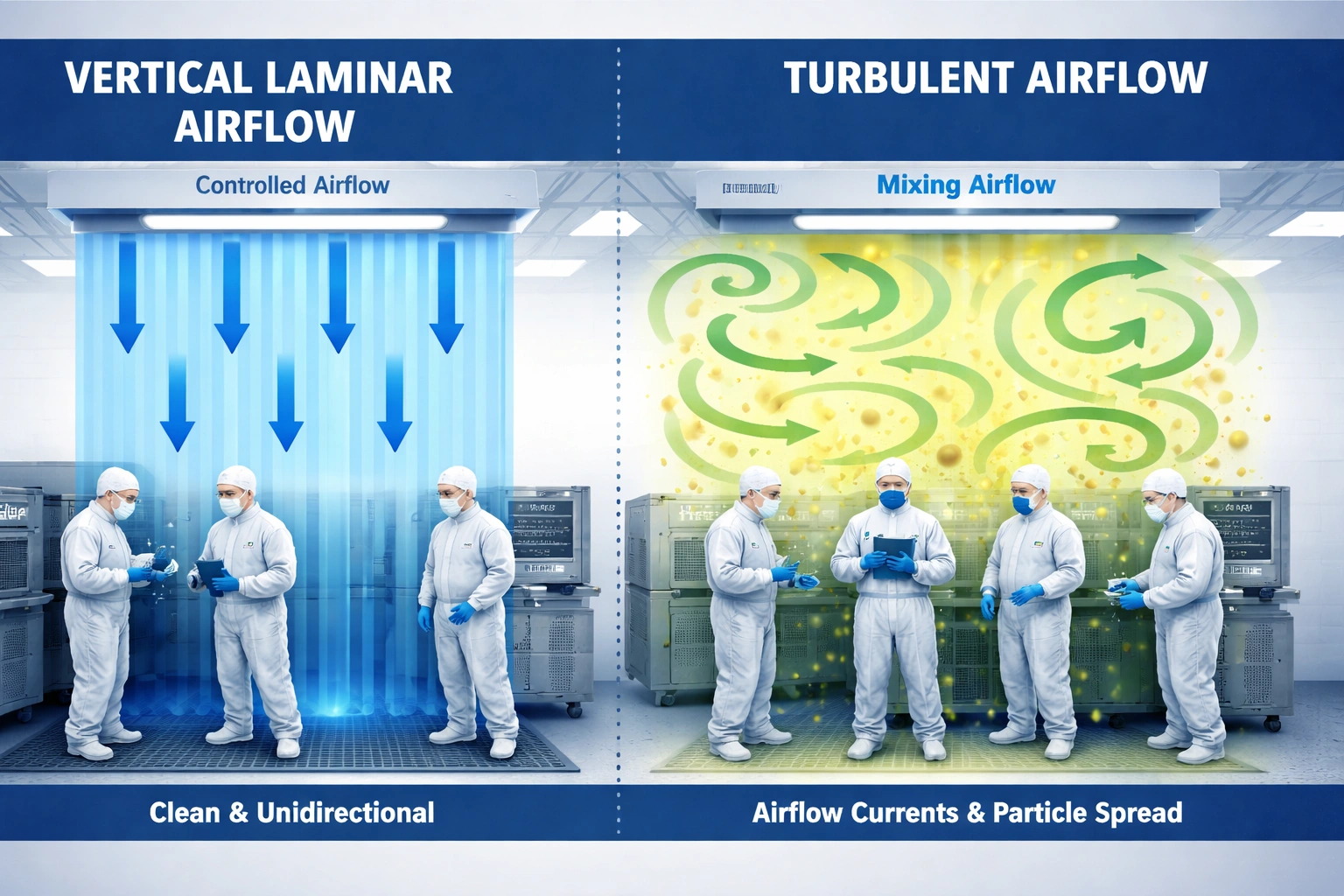
Cleanroom airflow patterns can be grouped into three practical categories: ideal laminar airflow, undesirable turbulent airflow, and short-circuit airflow. Your original content explains these distinctions clearly and they should remain central because they form the basis for all verification decisions. :contentReference[oaicite:3]{index=3}
| Zone | Expected airflow type | Typical velocity range | Uniformity expectation |
|---|---|---|---|
| Grade A / ISO 5 | Laminar | 0.36 ± 0.09 m/s | ±20% of mean |
| Grade B / ISO 7 | Laminar preferred | 0.1–0.4 m/s | ±20% of mean |
| Grade C / ISO 8 | Turbulent acceptable | 0.1–0.4 m/s | ±30% of mean |
| Grade D / ISO 9 | Turbulent acceptable | 0.1–0.4 m/s | ±30% of mean |
Visualization Methods
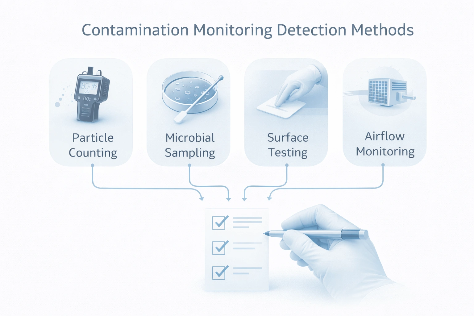
Your original article covers the two most practical methods well: smoke testing and particle trace methods. Smoke testing provides fast qualitative understanding of flow behavior, while particle tracing adds more quantitative evidence. In many facilities, using both creates the strongest verification package. :contentReference[oaicite:4]{index=4}
Smoke Test (Glycol Fog or Similar)
Purpose
Reveal actual airflow direction, turbulence, recirculation, and short-circuiting visually.
Strength
Fast, intuitive, and excellent for demonstrating flow patterns to QA, engineering, and auditors.
Limitation
Mainly qualitative unless combined with documented measurement and acceptance criteria.
Particle Trace Method
Purpose
Track particle movement and concentration changes across test points to support flow-pattern interpretation.
Strength
Adds numerical evidence and can help confirm where flow is bypassing or recirculating.
Limitation
Usually slower and more method-sensitive than smoke visualization alone.
Verification Procedures
Airflow verification should be performed against a defined protocol. Your original airflow verification protocol is strong because it includes pre-checks, per-filter observations, velocity mapping, and overall pass/fail logic. That structure should remain part of the published page because it turns the article into a practical tool, not just a description. :contentReference[oaicite:5]{index=5}
Pre-verification checks
- Personnel gowning verified
- Access conditions controlled
- HEPA operation verified
- HVAC and pressure differential checked
- Instruments calibrated
During verification
- Observe each HEPA or terminal unit
- Record laminar vs turbulent behavior
- Capture photographs or video
- Measure velocity at defined locations
- Document deviations immediately
Acceptance Criteria
Verification should not rely on subjective language alone. Your original article already defines useful acceptance points, including flow type, visible turbulence, short-circuiting, uniformity, and obstructions. These quantified criteria make the verification program more defendable. :contentReference[oaicite:6]{index=6}
| Kriterium | Krav | Acceptance | Metode |
|---|---|---|---|
| Flow type | Laminar / unidirectional | Required | Visual observation |
| Turbulence | No visible turbulence in critical zone | Required | Smoke visualization |
| Short-circuiting | No airflow bypass around critical zone | Required | Smoke visualization / particle trace |
| Velocity uniformity | Within ±20% of mean in Grade A | Required | Anemometer mapping |
| Obstructions | No airflow obstruction | Required | Visual inspection |
| Recirculation | No recirculation zones in critical areas | Required | Visual observation |
Common Airflow Issues
Your original issue table is useful because it connects frequency, root cause, and contamination impact. That makes the content more operational and more likely to attract linked references from validation and engineering teams. :contentReference[oaicite:7]{index=7}
| Issue | Typical frequency | Common root cause | Impact |
|---|---|---|---|
| Obstructions | Høj | Equipment placement, storage, personnel | Turbulence and reduced contamination control |
| Short-circuiting | Moderat | Poor airflow path, open doors, wrong layout | Critical zone bypass |
| Turbulence | Moderat | High velocity, obstruction, diffuser imbalance | Higher particle contamination risk |
| Non-uniform velocity | Sænke | Damper issues, filter degradation | Uneven protection |
| Recirculation | Sænke | Dead zones, poor return design | Particle accumulation |

Remediation Strategies
Once airflow issues are identified, the response should match the failure type. Your original remediation table is practical because it links issue type to action and timing. That approach is better than generic advice because facilities teams need fast prioritization. :contentReference[oaicite:8]{index=8}
| Issue | Recommended remediation | Typical timing |
|---|---|---|
| Obstructions | Reposition equipment, clear aisles, remove unnecessary items | Immediate |
| Short-circuiting | Adjust dampers, improve door control, install baffles | 1–2 days |
| Turbulence | Reduce velocity, remove blockage, adjust diffusers | 1–2 days |
| Non-uniform velocity | Rebalance airflow, check dampers, replace degraded filters | 2–3 days |
| Recirculation | Modify return design, add flow straighteners, review room layout | 1–2 weeks |
Dokumentation & Records
Verification is only defensible when documented. Your original article correctly highlights the need for protocols, observations, photographs, velocity maps, remediation records, and approvals. These are essential for both internal review and external audit readiness. :contentReference[oaicite:9]{index=9}
Verification protocol
Include method, acceptance criteria, instrument details, and scope of testing.
Visual evidence
Retain photographs or video showing airflow behavior at critical locations.
Velocity map
Document measured velocities, mean, and uniformity assessment.
Deviation and remediation record
Link failed verification to action, timeline, and re-test evidence.
Need Help Strengthening Airflow Pattern Verification?
Get practical guidance on smoke testing strategy, airflow acceptance logic, remediation priorities, and documentation systems that support audit-readiness and contamination control.
- Airflow verification framework support
- Laminar flow assessment logic
- Documentation and remediation guidance
Ofte stillede spørgsmål
How often should airflow pattern visualization be performed?
Grade A and ISO 5 areas are commonly verified annually, with additional testing after maintenance, equipment changes, airflow system changes, or contamination events.
What is the difference between smoke testing and particle trace methods?
Smoke testing is primarily visual and qualitative, while particle trace methods provide more quantitative information about particle movement and concentration behavior.
What velocity is typically expected for laminar airflow in Grade A zones?
A commonly used benchmark is 0.36 ± 0.09 m/s, but acceptance should always follow your validated site standard and applicable regulatory expectations.
How do I identify airflow short-circuiting?
Look for smoke or particle movement that bypasses the critical zone and moves directly from supply to return without protecting the intended area.
Can a room pass particle testing and still fail airflow verification?
Yes. Particle counts can look acceptable during one test while airflow remains unstable, obstructed, or vulnerable to operational disturbance.
What documentation is needed for audit-ready airflow verification?
At minimum: protocol, visual evidence, measured velocities, acceptance decision, deviations, remediation actions, and approval records.
Recommended Internal Links
- Cleanroom Maintenance Best Practices — airflow integrity depends heavily on HVAC and HEPA maintenance
- Renrum IQ OQ PQ Kvalifikation forklaret — airflow verification is a major OQ / PQ activity
- Validation Lifecycle Management — airflow must remain stable across the validated lifecycle
- ISO 14644 Classification Explained — airflow directly affects particle performance and classification capability
- Miljøovervågningssteder i GMP-renrum — airflow failure is a common contributor to EM deviations