A cleanroom mop is not a standalone product. It is an assembly of three interdependent components — head, frame, and handle — where dimensional tolerances, material compatibilities, and attachment mechanisms must be engineered as a matched set. When any component is sourced independently without verification, the consequences are not just inconvenience: they are contamination events, SOP deviations, and audit findings that are entirely preventable through system-level procurement.
A cleanroom mop system matters because the three components — head, frame, and handle — are structurally interdependent. The mop head attaches to the frame. The frame connects to the handle. The operator pushes the handle, which transfers force through the frame to the mop head against the floor. A dimensional or material mismatch at any of these two interface points changes the cleaning outcome: uneven floor pressure, incomplete coverage, component detachment, or particle generation from incompatible material contact. The system approach guarantees that all three components work together as designed. The standalone approach shifts that verification burden to the buyer — and to the operator who discovers the mismatch during use.
| Component Pair | What Happens If Mismatched | Operational Impact |
|---|---|---|
| Head → ਫਰੇਮ | Pocket too shallow → head slips off during mopping. Frame too narrow → incomplete floor contact, uneven pressure. Frame too wide → pocket stretches, tears at seams. | Contamination event (head detaches mid-cleaning). Cleaning inconsistency (missed areas). Premature head replacement (torn pockets). |
| ਫਰੇਮ → ਹੈਂਡਲ | Thread mismatch → handle won’t attach. Quick-connect with wrong receiver → incomplete lock, handle disconnects under pull force. Material incompatibility (SS handle + aluminum frame) → galvanic corrosion with certain disinfectants. | Operator safety risk (handle detachment). Tool unusable until correct connector sourced. Particle generation from corroded contact surfaces. |
| ਹੈਂਡਲ → Operator → ਫਰੇਮ → Head | Handle too short → operator bends, reducing stroke consistency. Handle angle incompatible with frame articulation → mopping pressure uneven. Combined effect: operator fatigue → cleaning quality degrades over shift. | Cleaning validation inconsistency (different operators produce different results with the same tool). Audit finding: “Cleaning procedure effectiveness not demonstrated under actual operator conditions.” |
The takeaway: Component compatibility is not a convenience — it is a contamination control variable. For a broader comparison of system-level vs component-level procurement approaches, see the cleanroom mop system vs flat mop comparison. For the foundational overview of what constitutes a mop system, see the ਕਲੀਨਰੂਮ ਮੋਪ ਸਿਸਟਮ ਦੀ ਸੰਖੇਪ ਜਾਣਕਾਰੀ.
Understanding why the full system matters requires understanding what happens at each interface point — the physical boundary where two components meet and must work as one. The following breakdown maps the three components and the two critical interfaces between them.
The textile cleaning surface. Its pocket dimensions (width and depth), pocket material strength, and fabric weight determine which frame widths it can accept, how much force the pocket can withstand during push-pull motion, and how the head’s weight interacts with the frame’s rigidity to produce consistent floor contact pressure.
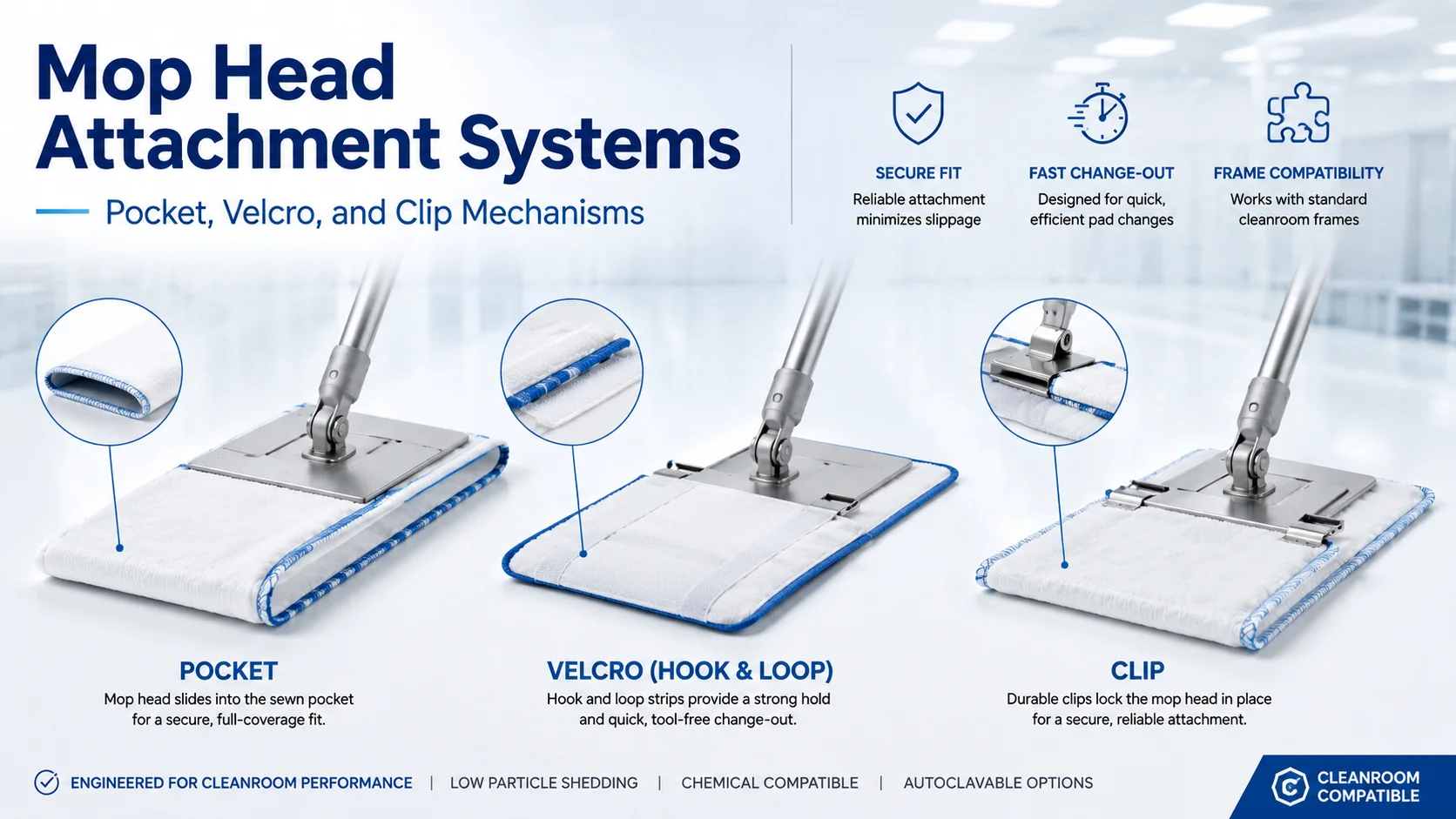
Key interface: Pocket opening ↔ Frame width. The pocket must be wide enough to accept the frame without forcing, deep enough to hold the frame securely during directional changes, and strong enough at the seam to resist tearing under repeated use.
For head material, weight, and sterility options, see the cleanroom mop head types and selection page. For weight-specific selection, see the cleanroom mop head weight guide.
The rigid structure that holds the mop head flat against the floor. Frame width, material (stainless steel, aluminum, composite), weight, and handle connector type determine which heads and handles are compatible — and how cleaning force is distributed across the mop head surface.
Key interfaces: Frame width ↔ Head pocket (Interface A). Handle receiver ↔ Handle connector (Interface B). The frame is the central component — it must match the head on one side and the handle on the other. A frame from Supplier A with a head from Supplier B and a handle from Supplier C has two potential mismatch points.
For frame material, width, and attachment type options, see the cleanroom mop frame types ਪੰਨਾ
The operator interface. Handle length, material, weight, grip design, and connector type determine operator comfort, mopping pressure consistency, and change-over speed. The handle is not a generic stick — its specifications interact with the frame connector and the operator’s biomechanics.
Key interface: Handle connector ↔ Frame receiver (Interface B). Threaded connectors must match thread pitch and diameter. Quick-connect systems must share the same locking mechanism design. A handle that connects securely on the workbench but disconnects under the pull force of mopping is a compatibility failure — not a product defect.
For handle material, length, and connector options, see the cleanroom mop handle selection ਪੰਨਾ

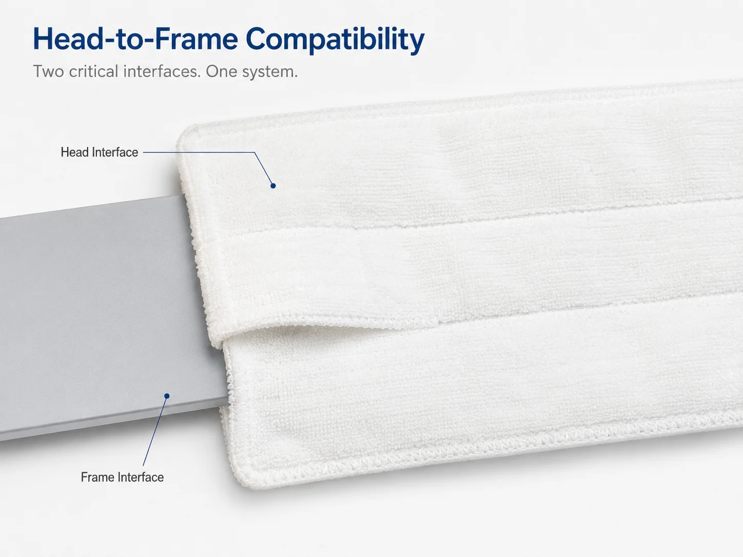
Of the two interface points in a mop system, head-to-frame is where most component mismatch failures occur. The reason is structural: the head is a textile product with tolerance ranges determined by fabric construction and stitching, while the frame is a rigid product with tight dimensional tolerances. When these two tolerance bands do not align, the result is either a head that slips during use or a frame that does not fully engage the head.
The mop head pocket is the fabric sleeve into which the frame is inserted. Two pocket dimensions determine frame compatibility:
| Dimension | What It Controls | Mismatch Consequence |
|---|---|---|
| Pocket width (side-to-side opening) | Whether the frame can be inserted at all, and how much lateral movement the head has once mounted | Too narrow: frame cannot be inserted. Too wide: head shifts laterally during directional changes, creating uneven floor contact and accelerated pocket seam wear. |
| Pocket depth (how far the frame penetrates into the head) | How securely the head grips the frame during push and pull strokes | Too shallow: head slips off the frame during the pull stroke — the most common component failure reported in GMP facilities. Too deep: excess fabric bunches at the frame edges, reducing effective cleaning surface area. |
The frame width must correspond to the mop head width. A 40 cm frame paired with a mop head designed for a 45 cm frame leaves 5 cm of unsupported fabric at each end — fabric that does not receive consistent cleaning pressure, creates drag, and may fold under the frame during use. Conversely, a frame that is wider than the head cannot be fully inserted, leaving the frame edges exposed and potentially contacting the floor directly.
The material pairing between frame and head affects friction, wear, and particle generation:
Real-world scenario: A facility ordered 65g mop heads and continued using existing 40 cm frames. The 65g heads were designed for 45 cm frames. The undersized frame did not fully engage the head pocket — only the center portion of the head received consistent pressure. Within two weeks, operators reported heads slipping during pull strokes. The facility attributed the failure to “poor head quality.” The actual cause was a dimensional mismatch that would have been caught had the head and frame been specified as a matched system.
While head-to-frame compatibility is the most visible failure point, handle-to-frame compatibility is the most overlooked. The handle connector is small, often standardized within a product family, and hidden from view once attached — but a failure at this interface means the operator loses control of the tool entirely.
| Connector Type | How It Works | ਫਾਇਦਾ | Failure Mode |
|---|---|---|---|
| Threaded (screw-type) | Handle threads into the frame receiver. Thread pitch and diameter must match. | Most secure connection. Resistant to pull-force disconnection. | Cross-threading if handle is not aligned before tightening. Thread wear over repeated assembly/disassembly. Incompatible thread standards between suppliers. |
| Quick-connect (spring-lock) | Handle pushes into receiver; spring-loaded pin or collar locks it in place. Release requires pressing a button or pulling a collar. | Fastest change-over. No threading required. | Incomplete lock if pin does not fully engage — handle appears connected but releases under pull force. Spring fatigue over time. Mechanism-specific — quick-connect Brand A does not work with Brand B. |
| Clip / Hook | Handle attaches via a clip or hook mechanism on the frame. | Simplest mechanism. Fewest moving parts. | Lowest pull-force resistance. Clip deformation over repeated use. Accidental release if mop catches on an obstacle. |
When the handle and frame are made from different metals — for example, a stainless steel handle connected to an aluminum frame — the contact point creates a galvanic pair. In the presence of an electrolyte (most cleanroom disinfectants qualify), galvanic corrosion can occur at the interface. The visible result is discoloration or pitting at the connection point. The functional result is a gradual weakening of the connector mechanism. This is a material science issue, not a product defect — but it can only be prevented if the handle and frame are specified as a matched set with verified material compatibility.
Handle length interacts with frame design to determine the operator’s body position during mopping. A handle that is too short forces the operator to bend forward, reducing stroke consistency. A handle that is too long changes the force vector — more horizontal push, less downward pressure. The ideal handle length depends on operator height, floor area, and the frame’s articulation angle. A system-specified handle is selected for the frame it pairs with and the cleaning task it performs. A standalone handle is selected for availability and price — and the ergonomic consequences are discovered during use.
The operational consequences of component mismatch are visible: slipping heads, disconnected handles, inconsistent cleaning. The documentation consequences are less visible but equally significant — especially during a GMP audit.
When an auditor reviews cleaning tool documentation, they are asking: “Is there documented evidence that the cleaning tools used in this facility are fit for purpose and used as validated?” The answer differs fundamentally depending on whether the facility uses an integrated system or independently sourced components.
The difference in audit preparation time between these two scenarios is measurable — and it compounds when the auditor asks follow-up questions about compatibility verification methodology, dimensional tolerance acceptance criteria, and material interaction testing. For structured guidance on the documentation that buyers should request from mop suppliers, see the cleanroom mop validation documents checklist. For a supplier-level audit framework, see the cleanroom mop supplier audit checklist.
The most commonly overlooked components in a cleanroom mop system specification are the bucket and wringer. While procurement teams carefully specify mop heads, frames, and handles, the bucket and wringer are frequently treated as generic janitorial accessories — purchased from a separate catalog, without specification, without compatibility verification, and without documentation.
This is a specification error with operational consequences. The bucket holds the cleaning solution that contacts every cleaned surface. The wringer determines the moisture level of the mop head — and moisture level directly affects cleaning efficacy, residue removal, and drying time. A bucket and wringer that are not specified to cleanroom standards introduce three contamination vectors into an otherwise validated cleaning protocol.
A cleanroom-grade bucket is not a container — it is a solution management system. Three design elements distinguish it from a janitorial bucket:
The wringer opening must be dimensionally matched to the mop frame width. An unmatched wringer applies uneven pressure — the center of the mop head is compressed more than the edges — producing inconsistent moisture levels across the cleaning surface. This inconsistency is not visible during mopping but results in variable cleaning efficacy and residue removal. For GMP environments where cleaning consistency must be demonstrated, an unvalidated moisture variable introduced by a generic wringer is an audit vulnerability.
A cleanroom-grade wringer provides calibrated pressure matched to the mop frame dimensions, producing consistent moisture removal across the full mop head width. This consistency supports the cleaning validation argument that the mop head condition is repeatable from stroke to stroke and from operator to operator.
A standard janitorial bucket used in a cleanroom introduces four failure modes:
A complete cleanroom mop system consists of five components — mop head, frame, handle, bucket, and wringer — working as a single validated workflow. The mop head attaches to the frame. The frame connects to the handle. The wringer removes solution from the head at a calibrated pressure matched to the frame width. The bucket holds the solution in a cleanroom-compatible container with documented material and cleanability. When all five components are specified as an integrated system, compatibility is ensured by design. When any component is sourced independently, that component introduces an unvalidated variable — and in a GMP environment, unvalidated variables are audit findings.
For a detailed bucket and wringer selection guide covering material grades, wringer types, single/dual/triple-bucket logic, and capacity planning, see the cleanroom mop bucket and wringer selection guide.
If your facility sources mop heads, frames, and handles from the same supplier as a matched system, the following checklist is the supplier’s responsibility, not yours. If you source components independently — or are evaluating whether to — this checklist is what you must verify before any component enters production cleaning.
Request supplier specifications for pocket width and depth. Measure frame width. Confirm that the frame inserts fully without forcing and that the head does not slip when pulled in the opposite direction of insertion. Document the verification result.
Identify the connector standard: threaded (record thread pitch and diameter), quick-connect (record brand and model), or clip (record dimensions). Confirm mechanical fit under both static and dynamic load — connect, then apply pull force equivalent to mopping resistance. Document the result.
If frame and handle are different metals, assess galvanic corrosion risk with the disinfectants used in your facility. If either component is composite or plastic, verify chemical resistance to your cleaning agents. Document the compatibility assessment.
Confirm that the head, frame, and handle can all withstand the sterilization method used in your facility (autoclave at specified temperature and cycle, gamma irradiation at specified dose, or EtO). A head that tolerates autoclave paired with a composite frame that warps at autoclave temperature is a system failure.
Each component supplier should provide: Certificate of Analysis or Certificate of Conformance, material composition statement, and sterilization compatibility documentation. If three suppliers provide documentation in three different formats, consolidate into a single audit-ready file before the cleaning tools enter service.
Verify the assembled system under your actual cleaning protocol: your cleaning agent, your operator technique, your floor surface. A component combination that passes bench verification may still fail under production conditions — and the production floor is not the place to discover this.
Document the specific component part numbers, supplier names, and the verification date in the cleaning SOP. If any component changes, the SOP must be revised and the new combination must be re-verified. This is the documentation link that auditors will check.
A simple table listing each approved head + frame + handle combination with verification date, verification method, and reviewer. This register is the first document an auditor will ask for if they identify that cleaning tools are sourced from multiple suppliers. See the GMP ਕਲੀਨਰੂਮ ਮੋਪ ਗ੍ਰੇਡ ਚੋਣ ਗਾਈਡ for how this register fits into the broader grade-based tool specification framework.
If you are executing this checklist for three components from three suppliers, you are doing the system integration work yourself — which means YOU own the compatibility risk. The system approach eliminates this checklist by design: the supplier guarantees compatibility, and the buyer verifies the supplier’s system-level documentation rather than performing component-level compatibility testing.
The following five mistakes represent patterns observed when facilities manage mop components independently rather than as an integrated system. Each is preventable through system-level procurement — and each has been documented in real facility operations.
“They are both standard flat mop heads — they should fit.” Pocket dimensions, strap configurations, and material thicknesses vary across manufacturers. A mop head that appears to fit on the bench may slip during the first pull stroke on the production floor. In a cleanroom, this is a contamination event, not a convenience issue.
Correction: Verify pocket dimensions against frame dimensions before procurement. If the head and frame are from different suppliers, perform a physical fit test under production conditions before deploying to all operators.
A facility switches from 55g to 65g mop heads. The head is thicker, the pocket is slightly different, and the frame — selected for 55g heads — does not engage fully. The operator notices the head feels loose but continues using it. This is how a procurement decision (let’s try heavier heads) becomes an operational problem (loose head on the frame).
Correction: When changing any component specification (head weight, material, or supplier), re-verify compatibility with all other components in the assembly before production deployment.
“A handle is a handle.” Facilities routinely replace broken handles with whatever is available in inventory — different length, different connector type, different material. The result: an operator using a handle that does not match the frame connector, either forcing a connection that damages the receiver or using an improvised attachment that fails under load.
Correction: Specify handle type, length, and connector as part of the mop system specification — not as a separately managed consumable. When a handle must be replaced, verify the replacement matches the original specification exactly.
The cleaning SOP lists: “Mop Head: Supplier A, Part #X. Frame: Supplier B, Part #Y. Handle: Supplier C, Part #Z.” There is no mention of whether these three components have been verified to work together. An auditor asks: “How do you know Part #X fits Part #Y?” The answer should be documented — not verbal.
Correction: If using multi-supplier components, include a compatibility verification record in the SOP appendix. Reference the component compatibility register (Checklist item 08) and the verification date. If using an integrated system, reference the system specification document and note that compatibility is supplier-guaranteed.
A stainless steel handle connected to an aluminum frame, used with an oxidizing disinfectant. Over six months, galvanic corrosion develops at the connection point. The handle becomes loose. The facility attributes the failure to “handle quality” and replaces the handle — with another stainless steel handle — repeating the cycle without addressing the root cause.
Correction: Assess material compatibility at both interface points during system specification. If using mixed metals, verify galvanic corrosion risk with the specific disinfectants used in the facility. Where possible, specify frame and handle in the same material to eliminate the galvanic variable entirely.
Component integration is one dimension of cleanroom mop system evaluation. The following related content on the MIDPOSI site addresses other dimensions of the system selection decision that interact with the component-level choices discussed in this guide.
The most common failure is head slippage during the pull stroke — the head detaches from the frame mid-cleaning. In a cleanroom, this is a contamination event. Less dramatic but equally problematic: an undersized frame that does not fully engage the pocket creates uneven floor pressure, leading to inconsistent cleaning coverage. The cleaning SOP assumes uniform contact; the mismatched tool delivers patchy results that may not be detected until environmental monitoring identifies an excursion.
Technically yes — if you verify dimensional compatibility, material compatibility, and sterilization compatibility before deployment. This verification is your responsibility, not the supplier’s. You must measure head pocket dimensions against frame width, test the attachment under production conditions, assess material interaction (galvanic corrosion, fabric abrasion), and document the verification results. If you perform this verification for every component combination in your cleaning program, a multi-supplier approach is operationally valid. If you do not perform this verification, you are accepting unresolved compatibility risk.
Handle connector type affects three operational variables: (1) change-over speed — quick-connect is fastest, threaded is slowest; (2) connection security — threaded is most secure under pull force, clip is least secure; (3) cross-supplier compatibility — threaded connectors from different suppliers may have different thread standards, quick-connect mechanisms are typically brand-specific. Facilities that value fast head change-over may prefer quick-connect. Facilities where handle disconnection would cause a contamination event in a critical zone may prefer threaded. The choice should match the operational risk profile of the cleaning zone.
At minimum: head pocket width and depth (from the head supplier), frame width and connector type (from the frame supplier), handle connector type and thread specification (from the handle supplier), and handle length. These four measurements determine physical compatibility. Additionally, verify: frame material and handle material (for galvanic corrosion assessment), sterilization compatibility across all components, and the maximum load rating of the connector mechanism if specified by the supplier.
Cleaning validation assumes that the tool used during validation is the same tool used during production cleaning. If a component changes — a different head weight, a different frame width, a different handle length — the validated cleaning conditions may no longer apply. The cleaning pressure, coverage pattern, and operator technique can all shift with component changes. A facility that validates with System X and then replaces the head with a different model without re-validating has introduced an unvalidated variable into a validated process. This is the documentation risk that the system approach eliminates: the system specification is the validated configuration, and any component change triggers a re-validation assessment.
A supplier offering an integrated mop system should provide: (1) a system specification document listing all components and confirming they are designed and tested as a matched set; (2) dimensional specifications for each component sufficient to verify fit; (3) material specifications for each component sufficient to assess chemical compatibility with common cleanroom disinfectants; (4) sterilization compatibility statements for each component; and (5) a Certificate of Analysis or Certificate of Conformance for the consumable components (mop heads). A supplier that cannot provide these documents for the system as a whole — only for individual components — is treating the components as standalone products, not as an integrated system.
Mixing components from different suppliers is acceptable when: (1) a documented compatibility verification has been performed and passed for the specific combination; (2) the verification covers dimensional fit, material interaction, and sterilization compatibility; (3) the verification is documented in the cleaning SOP or a companion compatibility register; and (4) a change control process is in place to trigger re-verification if any component in the combination changes. Without these four conditions, multi-supplier component mixing introduces undocumented variables into a process that requires documented control. For Grade A/B zones, the documentation burden of multi-supplier verification often outweighs the procurement flexibility benefit.
A system approach means you are locked into system-level compatibility — not necessarily into one supplier. If you switch to a different supplier’s system, the entire assembly (head, frame, handle) transitions together, maintaining compatibility. The constraint is that you cannot switch individual components independently without re-verification. This is not supplier lock-in — it is the logical consequence of component interdependence. A head designed for Frame A will only perform predictably with Frame A unless verified otherwise. The system approach acknowledges this reality and builds procurement processes around it. The standalone approach ignores it — and absorbs the consequences during operations.
Specify your cleanroom grades, cleaning surfaces, and workflow requirements. MIDPOSI provides matched head-frame-handle-bucket system recommendations with dimensional compatibility documentation for GMP audit readiness.
Documentation availability may vary by product configuration. Standard technical documentation provided with every inquiry.